Adam Romine
Projects
Currently I am working on two projects. The biggest project that I am working on is building the front suspension for the electric vehicle that the Central Washington University Electric Vehicle Club is building. This is the project that I am doing for my senior project. The other project that I am currently working on is building the steering column for the electric vehicle.


Electric Vehicle Front Suspension
Introduction
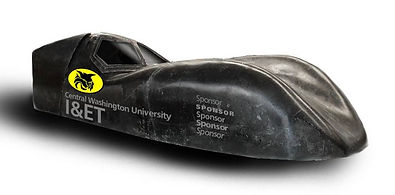
As fossil fuels become more scarce and more expensive the need for alternative means of transportation is growing. A huge push has been to create electric vehicles that do not rely on fosisl fuels to power them. This project is on making the front suspension for the electic vehicel that is being built by the Central Washington University Electric Vehicle Club.
Function
The function of the suspension will be a means to secure the two wheels to the front of the vehicle and attach a shock for a smoother ride. The suspension will also need to resist travel that would occur in the wheels and to smoothly transfer the load that happens during a corner.
Requirements
The design of my suspension system depends on two major factors. The first factor is whether or not the suspension will hold up to the forces that are going to be put upon it from the weight of the vehicle, and the forces acted upon it during corners. The next factor in the design is the requirements in the rule book for Electrathon America Competition. There are rules on how the suspension must be designed and the performance requirements that must be met.
-
The suspension needs to support the driver and vehicle of up to 500 pounds.
-
Must have the strength to not buckle the arm during maximum cornering force of 450lbf.
-
Must weigh less than 20 pounds per side.
-
The distance between the left and right wheel that is supported must be larger than 2 feet.
-
Needs to provide wheels with enough turning space for a 50 foot diameter turn.
-
Brackets installing the suspension need to withstand the force of 750 lb.
-
Must bolt onto the chassis that is already built.
-
Brackets must attach to the 1 in diameter bar of chassis.
-
Needs to provide a ground clearance of more than 2 in while trying to keep the vehicle as low as possible.
Design and Analysis
Optimization
This design will be optimized for simplicity, cost, and weight. Since there is limited time and man hours to complete this project keeping it simple will be of upmost importance. This project is on a limited budget so the price needs to be kept as low as possible. This can be optimized by choosing the least expensive material that will still meet the requirements stated in the requirement section. The weight of the suspension will also be optimized for.
Description
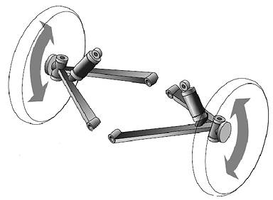
The swing arm suspension will be connected to the front of the chassis.
The swing arm that comes out will be pin connected to the brackets that are welded to the frame. The shock will come down from an attachment point that is higher up on the frame and attach to the end of the swing arm.
Failure Modes & Risk
How the suspension is expected to fail is at the control arm. As the vehicle is powering around corners the force is trying to buckle the arm. The safety factor for the arm is 3 but in order for the vehicle to not experience a force to great an operating constraint of a driver weight less than 250 pounds is required. There is risk that goes along with this device because if it fails it can cause the vehicle to lose control and crash. Since the vehicle will be traveling at relatively high speeds of about 40 MPH and is being driven by a person it could lead to injury of the driver that would be involved in the crash. To prevent crashes from occurring careful precautions must be made in the design to make sure that no failures occur during the use of this vehicle. Also proper maintenance of the shock will help make sure it stays in operational shape.
Methods and Construction
Construction
There were 26 parts in all that were assembled into 3 sub-assemblies and then come together fot the final assembly. All the parts were manufactured at the Central Washington University Machine Shop, and were put together in the Power Lab.
Manufacturing Issues
The biggest issue with this project was during the control arm bending and coping. First the material that was selected was a heat treated aluminum which I was told wouldn't work becuase it was going to build up to much residual stress during the bending. Next was the size of the steel I was recommended to use had too large of a diameter to fit the die for the bender. Lastly the bender didn't quite get me to the perfect 180 degree turn so I had to bend it using a vice which didn't allow me to hit my tolerances. Also while coping the arm in the milling machine it had excessive shatter which also didn't allow me to hit my tolerances.
Another issue was the CAD models of the Shock that I made were not exactly correct which caused some modifications to be made to the brackets in order for the shocks to fit in them.
Other than that the construction of this device went smoothly and was completed on time but exceeded predicted man hours.
Testing
Introduction
For testing the suspension on this vehicle assuming that the vehicle is functional when the suspension is put onto the vehicle an empty parking lot or racetrack will be needed to test out the vehicle and how it performs. What the tests will be looking for on the part is if the suspension transfers the load of the vehicle smoothly, if the parts break, and if it can last an hour of running time.
Methods
The first thing that will need to be done when the full suspension assembly is mounted onto the vehicle is configure the shock so that it performs appropriately. The shock will be tested using the methods described by the Fox Racing Company who are the manufacturers of the part. The next thing that will be tested is the strength of the suspension. The first thing that needs to be done is to test to make sure the suspension holds the weight of the driver and vehicle. The next test that will be done is a turning diameter test. The height of the vehicle will be tested by measuring the lowest part of the vehicle to the ground. The distance between the wheels will also be measured using a measuring tool.
Results & Discussion
It was determined that with the weight of the vehicle and the amount of travel that needed to occur in the shock under the static load was .438in. The closest psi number that gave this value was 135 psi. This gave an average travel value of .451in. The shock test data has a lot of errors in it because of how it was measured and the way the shocks were acting. The pump was tested to see how precise the readings were and while the readings were precise when the pump was unscrewed from the shock it would cause the shock to lose 5-10 psi. This was really affecting how accurate the readings were in the test. Another thing that was affecting the accuracy of the readings was the shocks would rebound to a different height each time. For information on this test refer to Appendix F figure 30. The rebound height would jump around by an average of .01in from the last reading. The wheel angle/ turning diameter test showed that the angle the wheels could make was 23 degrees which is much larger than the required 13.5 degree angle. Refer to Appendix F figure 31. The weight of the suspension was measured to be 12.3 pounds per side which is less than the required 20 pounds per side. Refer to Appendix F figure 32.
Budget & Scheduling
The estimated cost for this project was $99.49 dollars while the actual cost was $123.27. The added cost was a result of shipping costs and the extra material that was needed to by extra control arm material. Luckily the shocks were donated to the projects because they are valued at $300 dollars a piece.
The estimated time spent for this project was 154 hours while the actual time spen so far is 132 hours. The reason that the actual is less than the original is because of some of the assistance that I recieved while working on this project. I would like to thank Chris Nichols for the welding expertise. Professor Pringle, Professor Beardsley, Dr. Johnson, and Matt Burvee for help in design, analysis, testing, and manufacturing.
Conclusion
The results of this project are: 1) it functions as the function statement says that it should, 2) it doesn’t break when it is in use, and 3) the part is completed and tested in time for the Electrathon America Competition. Since the purpose of the suspension is to be bolted onto the electric vehicle so that it can race in the Electrathon America Competition these are reasonable results that would indicate a successful project. The Electrathon America Competition is going to take place in the spring of 2015.